I²C bus
I²C bus is an abbreviation for Inter Integrated Circuit bus or "I-Squared-C".
Some manufacturer call it TWI (Two-Wire-Interface) which is technically the same as I2C.
There is also SMBus. The I²C bus and the SMBus™ are essentially compatible with each other. Normally devices, both masters and slaves, are freely interchangeable between both buses. Both buses feature addressable slaves (although specific address allocations can vary between the two).
The buses operate at the same speed, up to 100kHz, but the I²C bus has both 400kHz and 2MHz
versions. Complete compatibility between I2C and SMBus is ensured only below 100kHz.
I²C is a serial and synchronous bus protocol. In standard applications hardware and timing are often the same. The way data is treated on the I²C bus is to be defined by the manufacturer of the I²C master and slave chips.
In a simple I²C system there can only be one master, but multiple slaves. The difference between master and slave is that the master generates the clock pulse. The master also defines when communication should occur. For bus timing it is important that the slowest slave should still be able to follow the master’s clock.
In other words the bus should be as fast as the slowest slave.
A typical hardware configuration is shown in the figure below:

Note that more slave chips can be connected to the SDA and SCL lines, normally Rp has a value of 1kOHM.
The clock generated by the master is called Serial Clock (SCL) and the data is called Serial Data (SDA).
![]() Always check if the pull-up resistors are connected !
Always check if the pull-up resistors are connected !
In most applications the micro controller is the I²C Master. Slave chips can be Real Time Clocks and Temperature sensors. For example the DS1307 and the DS1624 from http://www.maximintegrated.com .
Of course you can also create your own I2C slaves by programming an ATTINY or ATMEGA . See CONFIG I2CSLAVE
In that case there is AVR Master to AVR Slave communication.
LOGIC BUS LEVELS AND CONDITIONS

Data can only occur after the master generates a start condition. A start condition is a high-to-low transition of
the SDA line while SCL remains high. After each data transfer a stop condition is generated. A stop condition is a low-to-high transition of the SDA line while SCL remains high.

As said a data transfer can occur after a start condition of the master. The length of data sent over I²C is always 8 bit this includes a read/write direction bit, so you can effectively send 7 bits every time.
The most significant bit MSB is always passed first on the bus.
If the master writes to the bus the R/W bit = 0 and if the master reads the R/W bit = 1.
After the R/W bit the master should generate one clock period for an acknowledgement ACK.
Each receiving chip that is addressed is obliged to generate an acknowledge after the reception of each byte. A chip that acknowledges must pull down the SDA line during the acknowledge clock pulse in such a way that the SDA line is stable LOW during the HIGH period of the acknowledge related clock pulse.
After an acknowledge there can be a stop condition, if the master wishes to leave the bus idle. Or a repeated start condition. A repeated start is the same as a start condition.
When the master reads from a slave it should acknowledge after each byte received. There are two reasons for the master not to acknowledge. The master sends a not acknowledge if data was not received correctly or if the master wishes the stop receiving.
In other words if the master wishes to stop receiving, it sends a not acknowledge after the last received byte.
The master can stop any communication on the bus at any time by sending a stop condition.
BUS ADRESSING
Let’s say we have a slave chip with the address &B1101000 and that the master wishes to write to that slave, the slave would then be in receiver mode, like this:

You can see here that the master always generates the start condition, then the master sends the address of the slave and a “0” for R/W. After that the master sends a command or word address. The function of that command or word address can be found in the data sheet of the slave addressed.
After that the master can send the data desired and stop the transfer with a stop condition.

Again the start condition and the slave address, only this time the master sends “1” for the R/W bit. The slave can then begin to send after the acknowledge. If the master wishes to stop receiving it should send a not acknowledge.
OVERVIEW of Routines
Config Sda = Portx.x
Configures a port pin for use as serial data SDA.
Config Scl = Portx.x
Configures a port pin for use as serial clock SCL.
I2cinit
Initializes the SCL and SDA pins.
I2cstart
Sends the start condition.
I2cstop
Sends the stop condition.
I2cwbyte
Writes one byte to an I²Cslave.
I2crbyte
Reads one byte from an I²Cslave.
I2csend
Writes a number of bytes to an I²Cslave.
I2creceive
Reads a number of bytes from an I²Cslave.
I2C write and read:
A typical I2C write to send one byte of data looks like this:
I2cstart
I2cwbyte I2c_address_of_slave
I2cwbyte Byte_to_send
I2cstop
(I2cstart generates the start condition on the I2C bus were all devices are listen to. After this we send the Slave address of the device we want to send a byte to. The I2C slave with this address will send out a Ack where all other do nothing. Now you can start to send a byte (or more bytes) to this Slave address. After this an I2cstop release the bus.)
A typical I2C read to read one byte of data looks like this:
I2cstart
I2cwbyte I2c_address_of_slave
I2crbyte Databyte_to_read , Nack
I2cstop
(Nack indicates that the master do not want to read more bytes)
A typical I2C read to read one byte of data looks like this:
I2cstart
I2cwbyte I2c_address_of_slave
I2crbyte Databyte_to_read , Ack
I2crbyte Databyte_to_read , Nack
I2cstop
(Ack indicates that the master want to read more bytes from the slave and with the last byte to read the master indicate this with Nack)
I2C Software vs. Hardware Routines
By default BASCOM will use software routines when you use I2C statements. This because when the first AVR chips were introduced, there was no TWI yet. Atmel named it TWI because Philips is the inventor of I2C. But TWI is the same as I2C.
So BASCOM allows you to use I2C on every AVR chip. Most newer AVR chips have build in hardware support for I2C. With the I2C_TWI lib you can use the hardware TWI which has advantages since it require less code.
To force BASCOM to use the hardware TWI, you need to insert the following statement into your code:
$LIB "I2C_TWI.LBX"
You also need to choose the correct SCL and SDA pins with the CONFIG SCL and CONFIG SDA statements.
The TWI will save code but the disadvantage is that you can only use the fixed SCL and SDA pins.
![]() You only should include this library for a normal(older) AVR processor. Like Mega88. Do not include for Xmega, Xtiny, MegaX or AVRX.
You only should include this library for a normal(older) AVR processor. Like Mega88. Do not include for Xmega, Xtiny, MegaX or AVRX.
XMEGA
When using XMEGA, there is a difference : here you are supposed to use the hardware TWI. So that is a default. The reason is that Xmega has up to 4 different TWI-buses. There is no need to include a library. The only requirement is that you dimension a byte : Dim Twi_start As Byte
To force to the software solution, use $FORCESOFTI2C
XTINY/MEGAX/AVRX
These are all new AVR processors. The have a similar architecture as Xmega. For this reason, you are supposed to use the TWI hardware.
There is no need to include a library. The only requirement is that you dimension a byte : Dim Twi_start As Byte
See also:
Using USI (Universal Serial Interface), Config TWI, CONFIG TWISLAVE, I2C_TWI, $FORCESOFTI2C
I2CSEND , I2CSTART , I2CSTOP , I2CRBYTE , I2CWBYTE , I2C_TWI Library for using TWI
EXAMPLE with Software Routines
This example shows you how to setup and read the temperature from a DS1624 temperature sensor.
Connect the DS1624 like this:
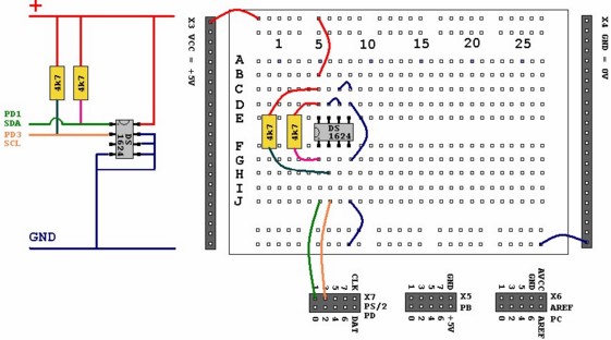
Then program this sample into your micro controller and connect your micro controller to the serial port of your PC.
$regfile = "m88def.dat" 'Define the chip you use
$crystal = 8000000 'Define speed
$hwstack = 40
$swstack = 30
$framesize = 40
$baud = 19200 'Define UART BAUD rate
' Declare RAM for temperature storage
Dim I2ctemp As Byte 'Storage for the temperature
' We use here the software emulated I2C routines
' Configure pins we want to use for the I²C bus
Config Scl = Portd.1 'Is serial clock SCL
Config Sda = Portd.3 'Is serial data SDA
I2cinit
' Declare constants - I2C chip addresses
Const Ds1624wr = &B10010000 'DS1624 Sensor write
Const Ds1624rd = &B10010001 'DS1624 Sensor read
' This section initializes the DS1624
I2cstart 'Sends start condition
I2cwbyte Ds1624wr 'Sends the address
'byte with r/w 0
'Access the CONFIG register (&HAC address byte)
I2cwbyte &HAC
'Set continuous conversion (&H00 command byte)
I2cwbyte &H00
I2cstop 'Sends stop condition
Waitms 25 'We have to wait some time after a stop
I2cstart
I2cwbyte Ds1624wr
'Start conversion (&HEE command byte)
I2cwbyte &HEE
I2cstop
Waitms 25
'End of initialization
Print 'Print empty line
Do
'Get the current temperature
I2cstart
I2cwbyte Ds1624wr
I2cwbyte &HAA 'Read temperature (&HAA command byte)
I2cstart
I2cwbyte Ds1624rd 'The chip will give register contents
'Temperature is stored as 12,5 but the ,5 first
I2crbyte I2ctemp , Ack
'So you'll have to read twice... first the ,5
I2crbyte I2ctemp , Nack
'And then the 12... we don't store the ,5
I2cstop
'That's why we read twice.
'We give NACK if the last byte is read
'Finally we print
Print "Temperature: " ; Str(i2ctemp) ; " degrees" ; Chr(13);
Waitms 25
Loop
End
You should be able to read the temperature in your terminal emulator.
Note that the used command bytes in this example can be found in DS1624 temperature sensor data sheet.
Example which use I2C Master hardware in AVR
See here: CONFIG TWI
I2C Practice (Tips&Tricks)
The design below shows how to implement an I2C-bus. The circuit is using a Mega88 as a master.
The TWI bus is used. While you can use any pin for software mode I2C, when a micro has TWI hardware build in, it is advised to use the TWI hardware.
R1 and R2 are 4K7 pull up resistors.
There are many I2C slave chips available. The example shows the PCF8574. With the additional TWI slave library you can make your own slave chips.

How to calculate Pull Up Resistor
The maximum of bus capacitance is 400pF (which is independent of bus speed 100KHz or 400KHz).
Here is a good article which describe how to calculate the Pull Up Resistor:
http://www.edn.com/design/analog/4371297/Design-calculations-for-robust-I2C-communications
Using AVR interal pull-up resistor (with Hardware Routines)
It is recommended to use external pull-up resistors !
For testing you could use also the AVR interal pull-up resistors
See example where Portc.4 and Portc.5 is SDA and SCL (the pull-up needs to be set after i2cinit):
i2cinit
Portc.4 = 1
Portc.5 = 1
Active Termination of I2C
The following information was submitted by Detlef Queck:
Many people have problems over and over with I2C(TWI) Termination. Use 4,7k or 10 k pull up? How long can the SCL, SDA line be when used with pull ups etc, etc.
You can simplify this confusing problem. Here is a Schematic for an active Termination of I2C and TWI. We have used this Schematic for over 10 years, and have had no problems with it. The I2C (TWI) lines can be up to 80cm (400KHz) without any problem when the Terminator is at the end of the lines.

How to handle longer cable length between I2C Master and Slaves or Multi-drop Configurations
The I2C-bus capacitance limit of 400 pF restricts practical communication distances. You can extend the use of the I2C in systems
with more devices and / or longer bus lengths with P82B715 or P82B96.
P82B96
| • | Isolates capacitance allowing 400 pF on Sx/Sy side and 4000 pF on Tx/Ty side |
| • | 400 kHz operation over at least 20 meters of wire (see AN10148) |
| • | Create Multi-drop configurations |
| • | Supply voltage range of 2 V to 15 V with I2C-bus logic levels on Sx/Sy side independent of supply voltage |
| • | Splits I2C-bus signal into pairs of forward/reverse Tx/Rx, Ty/Ry signals for interface with opto-electrical isolators and similar devices that need unidirectional input and output signal paths. |
P82B715
| • | Increase the total connected capacitance of an I2C-bus system to around 3000 pF and drive signals over long cables to approximately 50m |
| • | Multi-drop distribution of I2C-bus signals using low cost twisted-pair cables |
I2C Multiplexing, Switch and Voltage Level translation between different I2C busses
Some specialized devices only have one I2C or SMBus address and sometimes several identical devices are needed in the same system. The multiplexers and switches split the I2C bus into several sub-branches and allow the I2C master to select and address one of multiple identical devices, in order to resolve address conflict issues. An example is PCA9544A or PCA9546A (which also llows voltage level translation between 1.8 V, 2.5 V, 3.3 V and 5 V buses).
Your I2C (TWI) connection is not working (Tips&Tricks):
Checklist:
- Is the configured I2C clock frequency matching the frequency of the connected chip
- Check if you have pull-up resistors on SDA and SCL (and if the pull-up resistors are working)
- Do you have the right SDA and SCL pins conected ?
- connect also GND to have the same potential
- You can use the Err variable to check which I2C function is not working. When an error occurs, the internal ERR variable will return 1. Otherwise it will be set to 0.
- How about the voltage levels on both chips (do not connect 3.3V systems to 5V systems without voltage adapter)
- Is the system you are connecting the I2C to using a 7 Bit address or 8 Bit address (8-bit addresses include the read/write bit) ?
Then you can try with shift left:
' you can simply do this; &HC4 is an example address
const someI2caddress= &H4C * 2
' this would shift the address to the left.
- It is important that you specify the proper crystal frequency. Otherwise it will result in a wrong TWI clock frequency
- With following lib you do not use the software emulated TWI (I2C). You use the hardware I2C (for the AVR's that have an hardware I2C)
$lib "i2c_twi.lbx" ' we do not use software emulated I2C but the TWI
- By default BASCOM will use software routines for I2C.
- Do you have the right I2C read address ?
Here an example I2C write address which Bascom expects:
&B01000000 = &H40
Read address would be for this example:
&b01000001 = &h41
- In case of using TWI (I2C) Slave: Are you using the right library for your used chip ?
With the I2C TWI Slave add-on library you get both libraries:
| � | i2cslave.lib and i2cslave.lbx : This library is used for AVR‘s which have no hardware TWI/I2C interface like for example ATTINY2313 or ATTINY13. In this case TIMER0 and INT0 is used for SDA and SCL (Timer0 Pin = SCL, INT0 Pin = SDA). Only AVR' with TIMER0 and INT0 on the same port can use this library like for example ATTINY2313 or ATTINY13. The i2cslave.lib file contains the ASM source. The i2cslave.lbx file contains the compiled ASM source. See CONFIG I2CSLAVE below. |
| � | i2c_TWI-slave.LBX : This library can be used when an AVR have an TWI/I2C hardware interface like for example ATMEGA8, ATMEGA644P or ATMEGA128. In this case the hardware SDA and SCL pin's of the AVR will be used (with ATMEGA8: SCL is PORTC.5 and SDA is PORTC.4). This library will be used when USERACK = OFF. When USERACK =ON then i2c_TWI-slave-acknack.LBX will be used. See also Config TWISLAVE |
Operation at 400 kHz
Fast- mode devices can only be operated at 400 kHz clock frequency if no standard-mode devices (100KHz) are on the bus.
You can use an I2C Scanner to find I2C devices:
You basically use the Err variable. When an error occurs, the internal ERR variable will return 1. Otherwise it will be set to 0.
So 0 means we have found a I2C Slave with that address.
'------------------------------------------------------------------
' (c) 1995-2025 MCS
' i2cscan.bas
'purpose : scan all i2c addresses to find slave chips
'use this sample in combination with twi-slave.bas
'Micro: Mega88
'------------------------------------------------------------------
$regfile = "M88def.dat" ' the used chip
$crystal = 8000000 ' frequency used
$baud = 19200 ' baud rate
$hwstack = 40
$swstack = 30
$framesize = 40
Dim B As Byte
'we use the TWI pins of the Mega88
$lib "i2c_twi.lbx" ' we do not use software emulated I2C but the TWI
Config Scl = Portc.5 ' we need to provide the SCL pin name
Config Sda = Portc.4 ' we need to provide the SDA pin name
I2cinit
Config Twi = 100000 ' wanted clock frequency when using $lib "i2c_twi.lbx"
'will set TWBR and TWSR
'Twbr = 12 'bit rate register
'Twsr = 0 'pre scaler bits
Print "Scan start"
For B = 0 To 254 Step 2 'for all odd addresses
I2cstart 'send start
I2cwbyte B 'send address
If Err = 0 Then 'we got an ack
Print "Slave at : " ; B ; " hex : " ; Hex(b) ; " bin : " ; Bin(b)
End If
I2cstop 'free bus
Next
Print "End Scan"
End
I2C Slave Library
See I2C TWI Slave
I2C Slave LIB - how to Send/Receive more than 1 Byte for chips that do not have hardware I2C ?
Using following config:
Config I2cslave = &H34 , Int = Int0 , Timer = Timer0
When you want to receive/send multiple bytes, you need to keep track of them.
You can do this with a byte counter. this counter you would need to reset when the slave is addressed.
To do this the lib need to be altered:
- open i2cslave.lib with notepad
- look for label : I2c_adr_ack:
Then add this line :
rcall i2c_master_addressed
-then save and add this label to your code:
I2c_master_addressed:
Br = 0 'clear the byte counter
Bw = 0
return
in your code where the bytes are passed you can increase them.
The BR you increase when a byte is read, the BW you increase when a byte is passed.
for example:
I2c_master_has_data:
Incr Bw
Myarray(bw) = _a1
Return
Using ATXMEGA I2C with Software Routines (then you can choose the SDA and SCL Pins)
ATXMEGA have usually enough I2C interfaces. But nevertheless there is a possibility to use the I2C software routines and you can use any
Pin you want as SDA and SCL.
Following the ATXMEGA Master and below the ATMEGA328P I2C Slave which was tested with the ATXMEGA Master in I2C Software Mode:
Master
' Using ATXMEGA with software I2C routines to use also pins which are no hardware SDA/SCL pins
' Needed Library: $lib "i2c.lbx"
' The $forcesofti2c directive force the ATXMEGA to use software I2c/TWI Library
' The hardware for this example is XMEGA-A3BU XPlained board from Atmel
' Don't forget the pull-ups on SDA/SCL pin !
' Bascom Version 2.0.7.6 or higher needed
$regfile = "XM256A3BUDEF.DAT"
$crystal = 32000000 '32MHz
$hwstack = 64
$swstack = 40
$framesize = 80
$forcesofti2c ' with this the software I2C/TWI commands are used when inlcuding i2c.lbx
$lib "i2c.lbx" ' override the normal xmega i2c lib
Config Osc = Enabled , 32mhzosc = Enabled
Config Sysclock = 32mhz , Prescalea = 1 , Prescalebc = 1_1
Config Portr.0 = Output
Led0 Alias Portr.0 'LED 0 (XMEGA-A3BU XPlained board from Atmel )
Config Portr.1 = Output
Led1 Alias Portr.1 'LED 1 (XMEGA-A3BU XPlained board from Atmel )
Dim B As Byte
'We use here Virtual port 0
Config Vport0 = B ' 'map portB to virtual port0
Config Scl = Port0 .1 ' Pin to use as SCL (The hardware pin is Pinb.1)
Config Sda = Port0 .0 ' Pin to use as SDA (The hardware pin is Pinb.0)
I2cinit ' Bring the Pin's in the proper state
Do
Waitms 500
Set Led1
Reset Led0
Waitms 500
Reset Led1
Set Led0
Incr B
I2cstart
I2cwbyte &H24 ' address of I2C Slave
I2cwbyte B ' databyte to send to slave
I2cstop
Loop
End 'end program
Slave (for ATXMEGA using Soft I2C Master)
' I2C Slave Example for using with ATXMEGA
' ATMEGA328P running @ 3.3 Volt !
' Terminal output of this example when used with XMEGA_ise_soft_i2c.bas:
'(
ATXMEGA using Software TWI/I2C <------> ATMEGA 328P Bascom-AVR @ 3.3V...
>>> 180
>>> 181
>>> 182
>>> 183
>>> 184
>>> 185
>>> 186
>>> 187
>>> 188
>>> 189
>>> 190
>>> 191
')
$regfile = "m328pdef.dat"
$crystal = 12e6 '16MHz
$hwstack = 80
$swstack = 80
$framesize = 160
'CONFIG TWI SLAVE
Config Twislave = &H24 , Btr = 1 , Bitrate = 100000 , Gencall = 1
' With the CONFIG BTR, you specify how many bytes the master will read.
Dim Receive As Byte
Dim S As Byte
Enable Interrupts
Config Com1 = 19200 , Synchrone = 0 , Parity = None , Stopbits = 1 , Databits = 8 , Clockpol = 0
Wait 3
Print
Print "ATXMEGA using Software TWI/I2C <------> ATMEGA 328P Bascom-AVR @ 3.3V..."
Do
nop
Loop
End 'end program
'--------------------------------I2C--------------------------------------------
'Master sent stop or repeated start
Twi_stop_rstart_received:
Return
'We were addressed and master will send data
Twi_addressed_goread:
Return
'We were addressed and master will read data
Twi_addressed_gowrite:
Return
'this label is called when the master sends data and the slave has received the byte
'the variable TWI holds the received value
'Twi_btw is the BYTE NUMBER
Twi_gotdata:
Receive = Twi 'lesen
Print ">>> " ; Twi 'Print what we have received (ONLY FOR TESTING)
Return
'this label is called when the master receives data and needs a byte
'the variable twi_btr is a byte variable that holds the index of the needed byte
'so when sending multiple bytes from an array, twi_btr can be used for the index
'twi_btr is the BYTE NUMBER
Twi_master_needs_byte:
Return
'when the mast has all bytes received this label will be called
Twi_master_need_nomore_byte:
Return
'-------------------------------------------------------------------------------