The MCS EDBG programmer supports the Microchip EDBG programmers. We named it MCS EDBG Programmer since we implemented the EDBG protocol in BASCOM-AVR.
So what is an EDBG programmer? EDBG is a protocol for programming and debugging.
The ones that BASCOM supports must work in USB HID device mode.
Originally the SNAP programmer was used for testing but Microchip made an update to the firmware using a different protocol which is not supported.
You can still use the SNAP programmer but you need to replace the firmware. This means doing the recovery mode procedure, then using AS7 to load the firmware for AVR.
But it does not run out of the box and for this reason we do not recommend it for beginners. The SNAP programmer is however cheap and supports all AVR programmer modes.
Programmers can be obtained from Microchip. It does not require an additional windows driver since it is a so called HID device which is always supported.
You need the AVR UPDI license in order to use this programmer in BASCOM. Without UPDI license you can not code for the UPDI processors anyway.
The programmer should supports all Microchip EDBG UPDI programmers that identify as an Atmel device.
We tested with SNAP programmer V1, JTAGICE3, AVR128DB48-CNANO KIT and ATTINY817 Xplained. The explained series have an integrated programmer.
The new curiosity : AVR64DU32 Curiosity Nano is a cheap test board from Microchip that also has an integrated programmer. You can separate some tracks and use it to program other processors as well.
Details can be found in the documentation from Microchip.
The goal of the EDBG programmer support was to support UPDI mode. Some programmers support ISP and PDI mode. But BASCOM does not support these modes yet.
The ISP mode is in beta. It works for the ISP curiosity series. But no extensive tests were done.
The PDI mode is in beta as well. It is tested on the xmega128A3. The DAT files are not adapted and thus it will not work correct on processors with a different memory configuration.
The curiosity programmer only supports UPDI mode. SNAP supports all modes but does not work out of the box.
The great thing about EDBG programmers/hardware is that the protocol supports hardware debugging. BASCOM will support this too in a future version.
The programmer interface looks familiar:
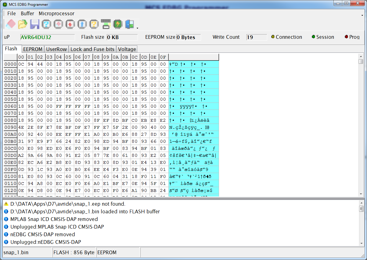
The FLASH TAB will show the content of the FLASH buffer. The content is loaded automatically when a BIN file exists of your project.
The EEPROM TAB will show the content of the EEPROM buffer. This is loaded automatically when an EEP file exists of your project.
The USERROW TAB will show the content of the USERROW buffer. This is loaded automatically when a USR file exists of your project.
The LOCK and FUSE Bits TAB is intended to program the various fuses.
The VOLTAGE TAB can be used to change the target voltage. But only when your programmer supports this.
The INFO window on the bottom will show if a programmer is found. In this case it is the SNAP ICD.
The yellow led will lit when there is a connection with a programmer.
The Session led will lt when there is a session active.
The Prog led wil lit when programming is active.
When using automatic programming the session is created and ended automatically.
When using manual programming you have the option (in Options, Programmer) to keep the session active. This to improve speed. On the other hand the programmer uses USB and the speed is great.
Each time you program the flash memory the write count is increased. The serial number is used and stored in the file named updiserials.prg. The MCS UPDI programmer uses the same file to keep track of writing.
Menu Options
Option |
Description |
File |
|
Exit |
Close programmer. |
Buffer |
|
Clear |
Clear buffer. Will put a value of 255 (FF hex) into each memory location. When the FLASH-TAB has the focus, the FLASH buffer will be cleared. When the EEPROM-TAB has the focus, the EEPROM buffer will be cleared. When the UserRow TAB has the focus the UserRow buffer will be cleared. 255 is the value of an empty memory location. |
Load from File |
This will show an open file dialog so you can select a binary file (BIN) or a HEX file in Intel HEX format. The file is loaded into the buffer. You can also manual edit the memory cells. |
Save to File |
Will save the current buffer to a BIN (binary) or HEX (hexadecimal Intel HEX) file. |
Reload |
Reloads the buffer from the file image. All programmers will always use the binary image to load files by default. |
Microprocessor |
|
Identify |
Will attempt to read the signature of the processor. When the signature is unknown(no DAT file available) or there is no chip or other error, you will get an error. Otherwise the processor name will be shown. |
Write buffer into processor memory |
This will write the active buffer(FLASH, EEPROM or UserRow) into the processor. |
Read processor memory into buffer |
When the chip lock bit is not set you can read the FLASH , EEPROM or UserRow memory into the buffer. |
Blank check |
Checks if the chip FLASH , EEPROM or UserRow is empty. |
Erase microprocessor |
Erases the processor FLASH. It depends on the fusebits if the EEPROM is erased too. Normally the EEPROM is erased too but some processors have a fuse bit to preserve EEPROM when erasing the chip. A processor MUST be erased before it can be programmed. |
Erase EEPROM |
Erases the EEPROM of the processor. The FLASH memory is not erased. When programming the EEPROM, all pages are automatically erased before programming. |
Unlock Microprocessor |
Unlocks the processor. This is a special ERASE option. When the processor is locked with its fuse bytes, you can not program the processor. You can only unlock/erase it. This will also erase the fuse bytes! |
Verify microprocessor memory with buffer |
Checks if the buffer matches the processor FLASH , EEPROM or UserRow. |
Auto program |
This will erase, and program the FLASH and EEPROM.
UPDI MODE When config FUSES is used in the code with the options set to ON, the lock and fuse bytes will be programmed too.
When there is no EEPROM image, the EEPROM will not be programmed.
For automatic fuse programming consider this : Config Fuses = On , Lock = Off , Fuse0 = &H00 , Fuse1 = &H64 , Fuse2 = &H00 , Fuse5 = &HD9 , Fuse6 = &H07 , Fuse7 = &H00 , Fuse8 = &H08
In this case automatic fuse programming is ON and all mentioned fuses will be programmed. Since LOCK is OFF , there will be no locks set.
While developing you best set the fuse options to OFF : Config Fuses = Off , Lock = Off , Fuse0 = &H00 , Fuse1 = &H64 , Fuse2 = &H00 , Fuse5 = &HD9 , Fuse6 = &H07 , Fuse7 = &H00 , Fuse8 = &H08
Remember, after locking a processor you need the UNLOCK option to be able to reprogram the processor.
ISP and PDI MODE $PROG directive is used for ISP and PDI programming. |
The Lock and Fuse bits TAB
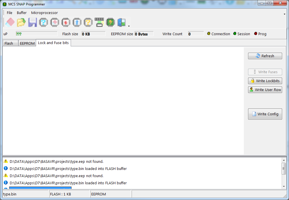
By default the lock and fuse bytes are not loaded. You need to click the REFRESH button to load the values.
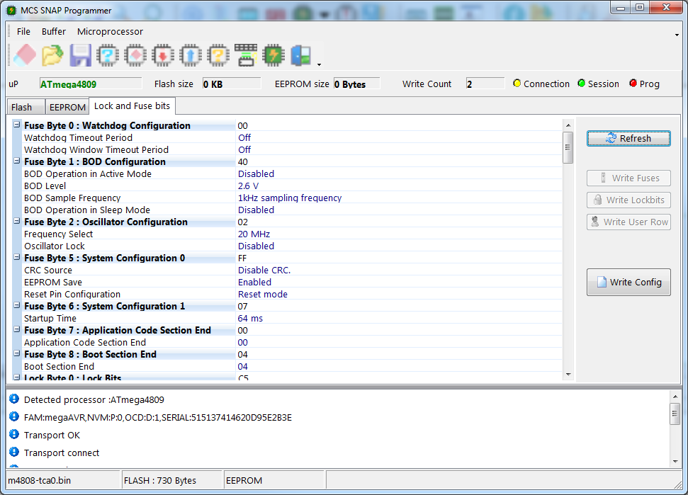
When you alter the value of a fuse, depending on the kind of fuse you alter, the WRITE FUSES button, WRITE LOCK BITS or WRITE USER ROW button becomes enabled.
Clicking the button will update the fuse value(s). And the Lock and Fuse bits are read again. Reading all values can take some time.
The WRITE CONFIG button will write the current Lock and Fuse bit value to the editor. That is : the value as read from the processor. This is NOT the value as you alter it.
The idea is that you first test the settings. When all works, you use the WRITE CONFIG button which will write a line like this to the current editor position :
Config Fuses=Off,Lock=OFF,Fuse0=&H00,Fuse1=&H40,Fuse2=&H02,Fuse4=&H00,Fuse6=&H07,Fuse7=&H00,Fuse8=&H04,UROW0=&H00,UROW1=&H00,UROW2=&H00,UROW3=&H00,UROW4=&H00,UROW5=&H00,UROW6=&H00,UROW7=&H00,UROW8=&H00,UROW9=&H00,UROW10=&H00,UROW11=&H00,UROW12=&H00,UROW13=&H44,UROW14=&H00,UROW15=&H00,UROW16=&H00,UROW17=&H00,UROW18=&H00,UROW19=&H00,UROW20=&H00,UROW21=&H00,UROW22=&H00,UROW23=&H00,UROW24=&H00,UROW25=&H00,UROW26=&H00,UROW27=&H00,UROW28=&H00,UROW29=&H00,UROW30=&H00,UROW31=&H00,UROW32=&H00,UROW33=&H00,UROW34=&H00,UROW35=&H00,UROW36=&H00,UROW37=&H00,UROW38=&H00,UROW39=&H00,UROW40=&H00,UROW41=&H00,UROW42=&H00,UROW43=&H00,UROW44=&H00,UROW45=&H00,UROW46=&H00,UROW47=&H00,UROW48=&H00,UROW49=&H00,UROW50=&H00,UROW51=&H00,UROW52=&H00,UROW53=&H00,UROW54=&H00,UROW55=&H00,UROW56=&H00,UROW57=&H00,UROW58=&H00,UROW59=&H00,UROW60=&H00,UROW61=&H00,UROW62=&H00,UROW63=&H00
The CONFIG FUSES line only contains values that differ from &HFF meaning that one of the bits is set.
By default FUSES and LOCK are always set to OFF. This means that the programmer will not process the fuses and locks.
When your project is done and you want to program more processors you can change the FUSES=OFF into FUSES=ON. Then recompile so this info is written into the project PRG file. And now when you auto program the processor, the fuses are also programmed.
The same applies for the locks : when you want to lock the processor, you change LOCK=OFF into LOCK=ON, then recompile. When you program the processor, the lock byte(s) is also programmed.
When the lock byte is set, only an UNLOCK allows to reprogram the processor. UNLOCK will erase the processor. So all content (EEPROM too) will be erased.
Some processors have a large UserRow memory. For this reason you can also program the UserRow using the UserRow TAB.
USERROW
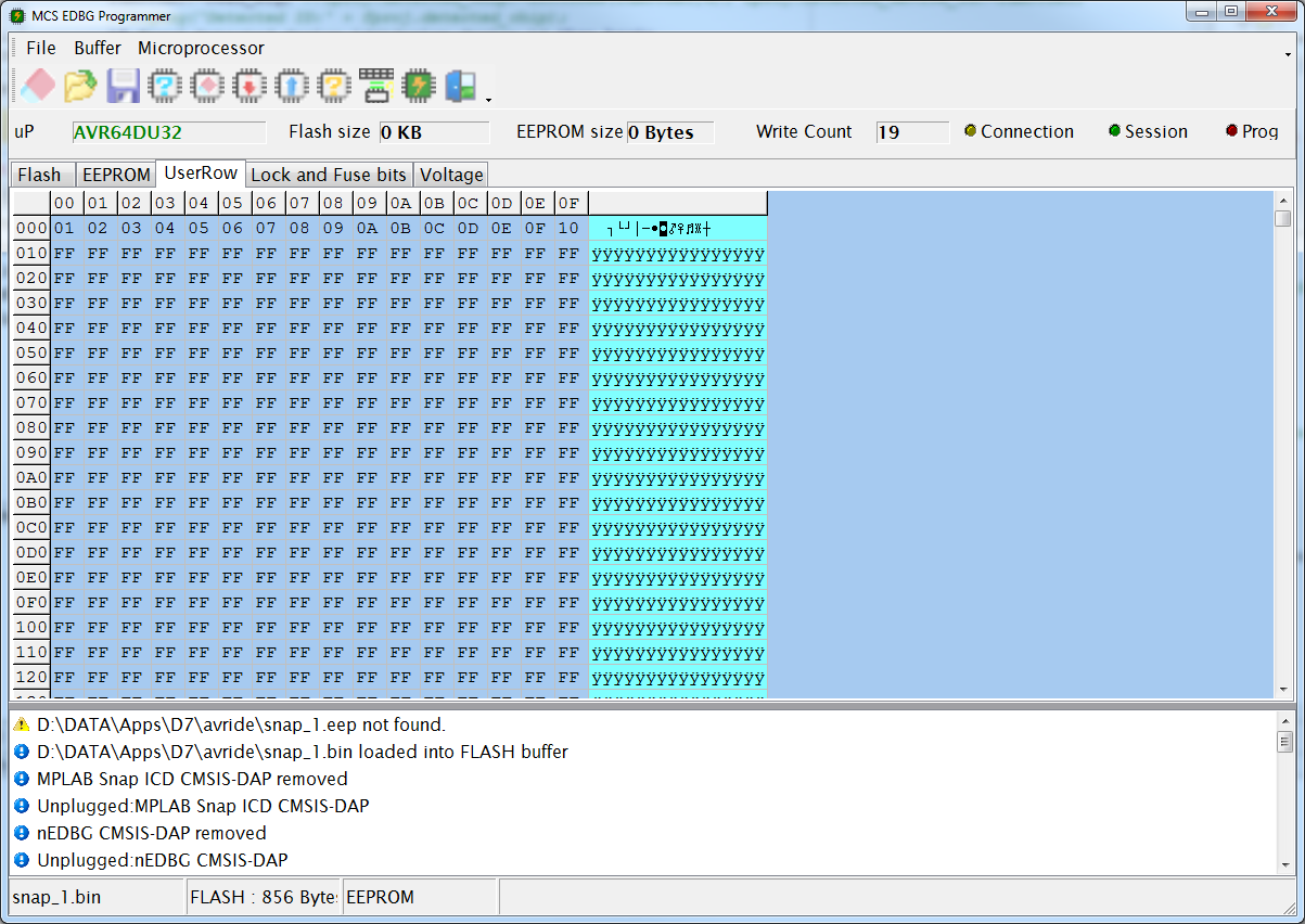
It works just the same as the EEPROM TAB.
When you create a binary .USR file the content is loaded automatically into the buffer.
Use the $USER directive in combination with DATA lines to create the binary .USR file.
Voltages
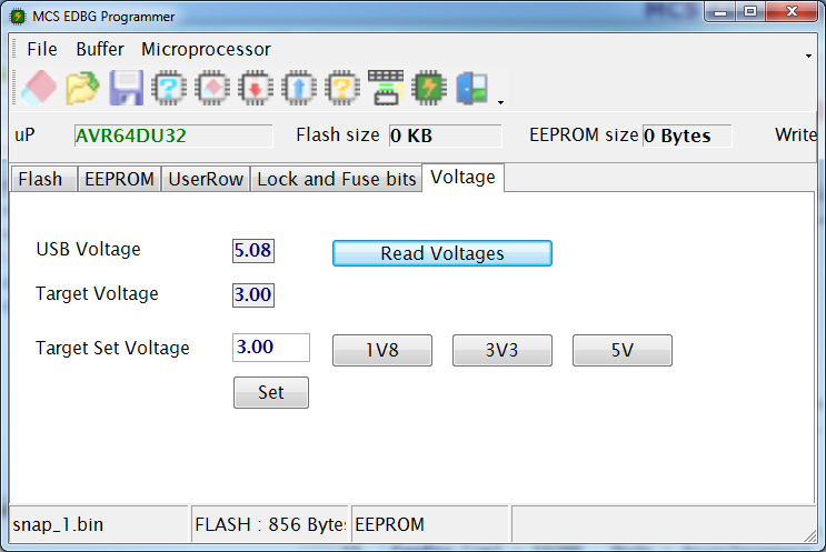
The voltages TAB can read the USB voltage and the target voltage. When the programmer supports it you can also set the target voltages.
Use the 1V8, 3V3 and 5V preset buttons to set the voltage. Click the SET button to actual set the voltage.
PIN |
DESCRIPTION |
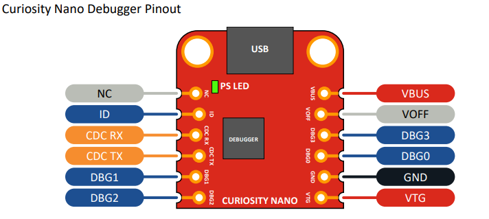
NC |
Not connected |
ID |
ID line for extension |
CDC RX |
USB CDC RX line |
CDC TX |
USB CDC TX line |
DBG1 |
Debug clock line |
DBG2 |
Debug GPIO0/SW0 |
VBUS |
VBUS voltage for external use |
VOFF |
Voltage Off input. Disables the target regulator and target voltage when pulled low. Make it low to activate. |
DBG3 |
Reset Line |
DBG0 |
Debug data line. Connect to UPDI of the target processor |
GND |
Common ground. |
VTG |
Target Voltage |
For programming you connect GND to GND of the target. Connect VTG to the target processor when your target circuit does not need much power. Do not connect when your target has it's own power.
And connect DBG0 to the UPDI pin of the target processor. Optional you can connect DBG3 to the reset pin of the processor. Most processors have a fuse that must be programmer first in order to select reset for the pin. Otherwise it is just a normal pin.
The image shown is the programmer part of the curiosity board. You need to separate the PCB before you can use it to program other processors. Instruction on how to cut tracks you can find in the documentation of the curiosity board. By default the programmer/debugger is connected to the on board target processor. When you cut tracks or board you need to make wired connections in order to program in again.
The ISP mode was tested with both Xplained boards : Xplained 168PB and Xplained 328PB.
The ISP mode has a fixed clock frequency for most boards we tried. In AS7 you will also not find a way to change the clock.
SNAP programmer info
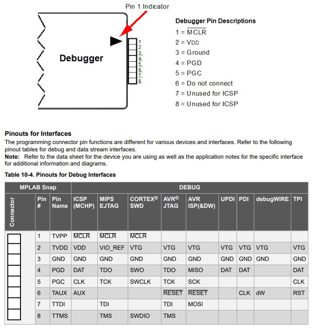
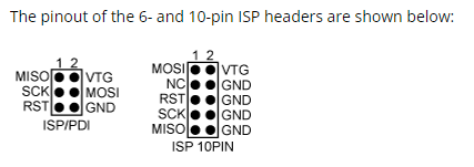
For all supported mode you need to connect GND(ground) to pin 3 and VTG(vcc) to pin 2.
For UPDI you also need to connect the DAT to pin 4.
For ISP you need to connect MISO to pin 4, CLOCK to pin 5, reset to pin 6 and MOSI to pin 7.
For PDI you need to connect DAT to pin 4 and RESET to pin 6. While the table shows CLK for pin 6, it is actually connected to the RESET pin of the ISP connector.
![]() There is no option to select ISP, UPDI or ISP mode. The mode depends on the DAT file value from the $REGFILE directive in your code.
There is no option to select ISP, UPDI or ISP mode. The mode depends on the DAT file value from the $REGFILE directive in your code.
See Also